

The strategic installation of insulating components and barriers can minimise the impact of wildlife on power grid assets. If these components are specified correctly, such modifications can minimise costly power outages while reducing fire risk and safeguarding assets and the environment for 40 years or more.
Localised fires caused by the interference of animals (such as birds, possums, bats, rats, snakes and more) with high-voltage overhead lines and substations – and the uncontrolled bushfires that can result on the ground below – are a pervasive problem for electric utilities and industrial power-distribution systems all over the world. Such incidents result from:
- Wildlife-related activities, including ignition nesting materials and other animal-related debris, pole-top fires, and electrocuted birds and animals falling to the ground, igniting dry vegetation below.
- Vegetation-induced fire resulting from live bare conductors clashing with dry vegetation.
- Conductor clashing, where two adjacent conductors come in contact with each other, generating sparks, conductor damage and travelling arcs.
- Flashover of pollution (such as bird guano and airborne environmental pollutants) that has built up on insulated components. Such materials can create a conductive path for current to flow through, increasing the risk of arcing, flame tracking and flashover.
In general, fire-related outages caused by wildlife and vegetation are categorised in two categories; both types of risk can be mitigated with the installation of appropriate insulated Wildlife Asset Protection (WAP) components:
- Phase-to-earth faults. These occur when the presence of wildlife or debris forms a conductive pathway that connects the equipment phase to the ground.
- Phase-to-phase faults. These occur when two adjacent phases collide or are momentarily connected via wildlife or debris (for example, during wire-clashing incidents), producing hot, molten metal particles that can ignite dry materials nearby.
You may ask, what is a Wildlife Asset Protection (WAP) component? These are insulating covers and barriers, which are used to mitigate risk on uninsulated overhead and substation components.
Proper material selection is especially critical – and often-overlooked – during the selection of reliable, retrofittable WAP components.
If careful consideration is not given to selecting the most appropriately formulated engineering polymers for these insulated components, they can still be susceptible to degradation, premature failure, ignition and fire propagation. This is discussed in detail below.
The business case for installing the right WAP upgrades
While the investment needed to reduce the risk of wildlife-related fire and bushfire risk is too often deemed discretionary or reactionary, efforts to improve fire safety and enhance operating reliability provide demonstrable payback for utility owners, by helping them to avoid the costly and catastrophic implications of wildlife-related fires, including:
- Human injuries and loss of life
- Damage to (and loss of) power grid assets
- Service interruptions and power outages (SAIDI and SAIFI impact), which can threaten not only individual homes and communities, but create potentially hazardous conditions at hospitals, industrial facilities, schools and more
- Environmental hazards and potentially life-threatening danger to personnel if the bushfire leads to potentially hazardous materials to the environment
- Catastrophic damage to agricultural and horticultural assets
- Regulatory repercussions related to penalties, fires and litigation
- Negative media and social media attention, creating reputational damage and damage to shareholder value
For most utilities, the ability to avoid even one potential outage can help to underwrite the costs to upgrade the system with appropriate protections.
The particular combination of WAP components needed to fortify each site is customised based on the particular challenges and assets encountered at that location.
Material considerations for WAP components
Not all engineering polymers are able to guarantee the same type of fire protection – and, importantly, the level of fire prevention – that is needed to effectively mitigate actual fire risk. During selection and specification of WAP components to reduce fire risk in overhead lines and substations, close consideration must be given to selecting polymeric formulations that can withstand the harsh operating conditions most overhead lines and substations routinely experience – including high-voltage stress, pollution buildup, pollution-induced arcing, flashover, elevated temperatures and mechanical stress.
Insulated components that are not manufactured from the most appropriate performance polymer face gradual degradation over time, have elevated risk of tracking, embrittlement due to ultraviolet (UV) damage, melting due to poor thermal resistance, and ignition due to poor arc resistance.
To this end, the three most critical material science performance attributes to consider when specifying WAP components are:
1. Tracking and erosion resistance (TERT)
TERT provides a measure of a material’s tracking resistance, which is its ability to withstand surface arcing and ignition under a high stress environment.
A material’s TERT rating is demonstrated using the ASTM D2303 abrasion test method, Step Method (2.5–3.25-kV) test method. Polymeric materials that exhibited insufficient tracking resistance (according to TERT) tend to present a higher risk of longer-term degradation over time, which leads to insulation breakdown, increased spark production and flame propagation.
Per the ASTM standard, a material is considered to have good to excellent TERT resistance and overall resiliency if it can survive more the STEP TERT using abrasion method during this destructive test.
2. Ultraviolet (UV) resistance
UV resistance provides a measure of a polymer’s ability to withstand damage and failure over time from prolonged UV exposure in outdoor environments.
Polymeric components that have poor UV resistance experience surface roughening over time, and this makes it easier for environmental pollutants to accumulate (thereby increasing the risk of arcing, tracking and ignition associated with pollution buildup).
UV resistance is demonstrated using the ASTM G154, Cycle 3, UV-3 test method at a minimum test duration of 1,000 hours.
However, as a better predictor of UV performance over a 30+ year lifecycle, operators should insist on a polymer that has been UV tested for 5,000 hours or more.
3. Thermal endurance
A polymer’s thermal endurance rating provides a measure of a material’s ability to maintain its mechanical integrity (that is, to resist melting and deforming) in the face of sustained elevated temperatures.
The ability to withstand melting and dripping also helps to reduce risk (as hot plastic dripping on dry vegetation below can trigger a bushfire).
Thermal endurance on insulating covers is typically demonstrated using two test methods:
- Thermal Index IEC 60216/IEEE 98 at 105°C (221°F), which demonstrates a material’s thermal performance for 20,000 hours, and
- Thermal Aging ASTM D2671 750 hours at 150°C (221°F), which is a useful indicator of life expectancy and ties the material’s tested performance attributes to a service life of 30 years or greater
An improved testing methodology
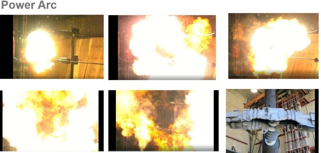
To demonstrate these three essential material properties, this company uses a power-arc testing methodology, as recommended in IEEE 1656.
This test simulates the challenging conditions of a power arc in service —generating high voltage, high energy, high temperatures and hot gases in a short period of time.
This is shown in the photos in the image below. This test adequately simulates potential ignition scenarios that could actually arise quickly in a power-distribution system, where a high-energy burst from a lightning strike, trapped arc root or fault current is likely to confront the system and individual polymeric components.
Such a test is deemed successful if the polymeric WAP component remains intact following the arc exposure and does not deform or catch fire.
Closing thoughts
To safeguard overhead lines and substations from the risk of unplanned outages and wildlife-related fires, utility owners should partner with an experienced vendor and develop a strategic plan to replace, retrofit and/or upgrade the most at-risk components and enhance insulation throughout the system based on a structured risk assessment process.
Trust should be placed in partners with a proven track record of experience in the field, broad expertise in electrical and mechanical component design, and material science. Partner with a company that has fully integrated compounding, supply-chain integration, testing and installation, and materials science expertise, as this can help to reduce cycle time and support troubleshooting and quality-control as well as customer-service initiatives.
Important test methods to validate polymer performance in WAP components
Mechanical performance attributes:
- Tracking and Erosion Resistance (TERT), per ASTM 2303, STEP TERT, (abrasion method)
- This test aligns with contamination and leakage current that will cause a wildlife cover to track flames, compromising its insulating properties over time
- UV Performance, per ASTM G154 (5,000-hour duration)
- This test assesses the damage from UV exposure in intense environments, and provides a proxy for 35+ life expectancy
- Thermal Index IEC 60216 / IEEE 98 at 105°C (20,000-hour duration)
- This test aligns with long-term product performance and accelerated aging, linking it to the life-cycle performance of the component
- Thermal Aging ASTM D2671 at 150°C (750-hour duration)
- This test aligns with predicting life expectancy, and ties the material’s tested values to real-life data from 30 years of actual service life in the field
Electrical performance attributes:
- Wet Withstand IEEE-4-1995 and IEEE 1656-2010 (Guide), Fixed Electrode
- This test demonstrates a material’s ability to protect against animal contact up to 35kV
- Wet Power Frequency Flashover & Lightning Impulse Withstand IEEE-4-1995 and IEEE 1656-2010 (Guide)
- This test demonstrates whether a cover affects the electrical perform of the insulator that it is covering
- Power Arc Test-10 kA, 10 cycles, IEEE-1656 (Guide)
-
-
- This test demonstrates the ability of a cover to withstand extreme bursts of energy, and its ability to not ignite or hold a flame
-
-
This partner content is brought to you by TE Connectivity. For further details on these solutions please get in touch with your local TE representative or email [email protected].


